BeagleBone Green Getting Started
How to get started with a BeagleBone Green (BBG) including installation, internet, GPIO, device tree, Si5351 interface via i2c and cross compiling the kernel.
1. Getting Started
Instructions for getting started with the BBG are available at at at https://beagleboard.org/getting-started. This involves downloading the Debian Linux image and writing it to a microSD card (make sure you use the Debian image for the BBG). My version was:
Buster IoT (without graphical desktop) for BeagleBone and PocketBeagle via microSD card
AM3358 Debian 10.3 2020-04-06 4GB SD IoT image for PocketBeagle, BeagleBone, BeagleBone Black, BeagleBone Black Wireless, BeagleBone Black Industrial, BeagleBone Blue, SeeedStudio BeagleBone Green, SeeedStudio BeagleBone Green Wireless, SanCloud BeagleBone Enhanced, Arrow BeagleBone Black Industrial and Mentorel BeagleBone uSomIQ - more info - sha256sum: 22448ba28d0d58e25e875aac3b4e91eaef82e2d11c9d2c43d948ed60708f7434
The driver for networking via USB didn’t work with the latest version
of MacOS (Big Sur 11.2.1) but the BBG was able to use DNS over Ethernet
to connect to my network (this won’t work in the lab if there is more
than one BBG plugged into the network). One can then run ssh to access (use “temppwd” as the
password for user “debian”)
debian@beaglebone:~$ ssh -Y [email protected]
Debian GNU/Linux 10

BeagleBoard.org Debian Buster IoT TIDL Image 2020-04-06

Support: http://elinux.org/Beagleboard:BeagleBoneBlack_Debian

default username:password is [debian:temppwd]

[email protected]'s password:

The programs included with the Debian GNU/Linux system are free software;
the exact distribution terms for each program are described in the
individual files in /usr/share/doc/*/copyright.

Debian GNU/Linux comes with ABSOLUTELY NO WARRANTY, to the extent
permitted by applicable law.
Last login: Mon Feb 22 22:27:56 2021 from 192.168.0.32
debian@beaglebone:~$
2. Internet Connection
Drivers to support Internet via USB on the BeagleBone (see Getting Started) cannot be installed on MacOS e.g. Big Sur 11.2.1. Fortunately, the BBG uses standard Linux networking so this is easy to solve. In the examples that follow, the host Mac machine has the prompt “phwl@PHWL-MBP ~ %” and the BBG prompt is “debian@beaglebone:~$”. The same instructions should work for other Beaglebone Boards like the Pocket Beagle or BeagleBone Black.
1. Connecting via Ethernet
1.1a. On MacOS
Connect your Mac to the BBG using the microUSB. Connect your BBG Ethernet port to a network switch via an Ethernet cable.
Use screen to login to the BBG from your Mac via
the USB connection (use the one attached to the microUSB connector).
phwl@PHWL-MBP ~ % screen /dev/cu.usbmodemBBG2200804786
1.1b. On Windows
Connect your PC to the BBG using the microUSB. Connect your BBG Ethernet port to a network switch via an Ethernet cable.
Right click the Windows menu and select “Device Manager”. After the BBG has registered the new USB device, Under “Ports (COM & LPT)” you should see “USB Serial Device (COMx)” where x is a number. In my case it was COM3.
Download, install and run Putty. To login to the BBG from your PC via the USB connection (use the one attached to the microUSB connector) you select “Serial” as the Connection Type and use your com port (e.g. COM3) as the “Serial line” and click Open.
2. Connecting via Wifi
You can also connect the BBG to a Mac and then share its wifi with the BBG.
2.1. MacOS
Connect your Mac to the BBG using the microUSB. Connect your BBG Ethernet port to the Mac’s Ethernet using an Ethernet cable (you will need an Ethernet adaptor for your Mac).
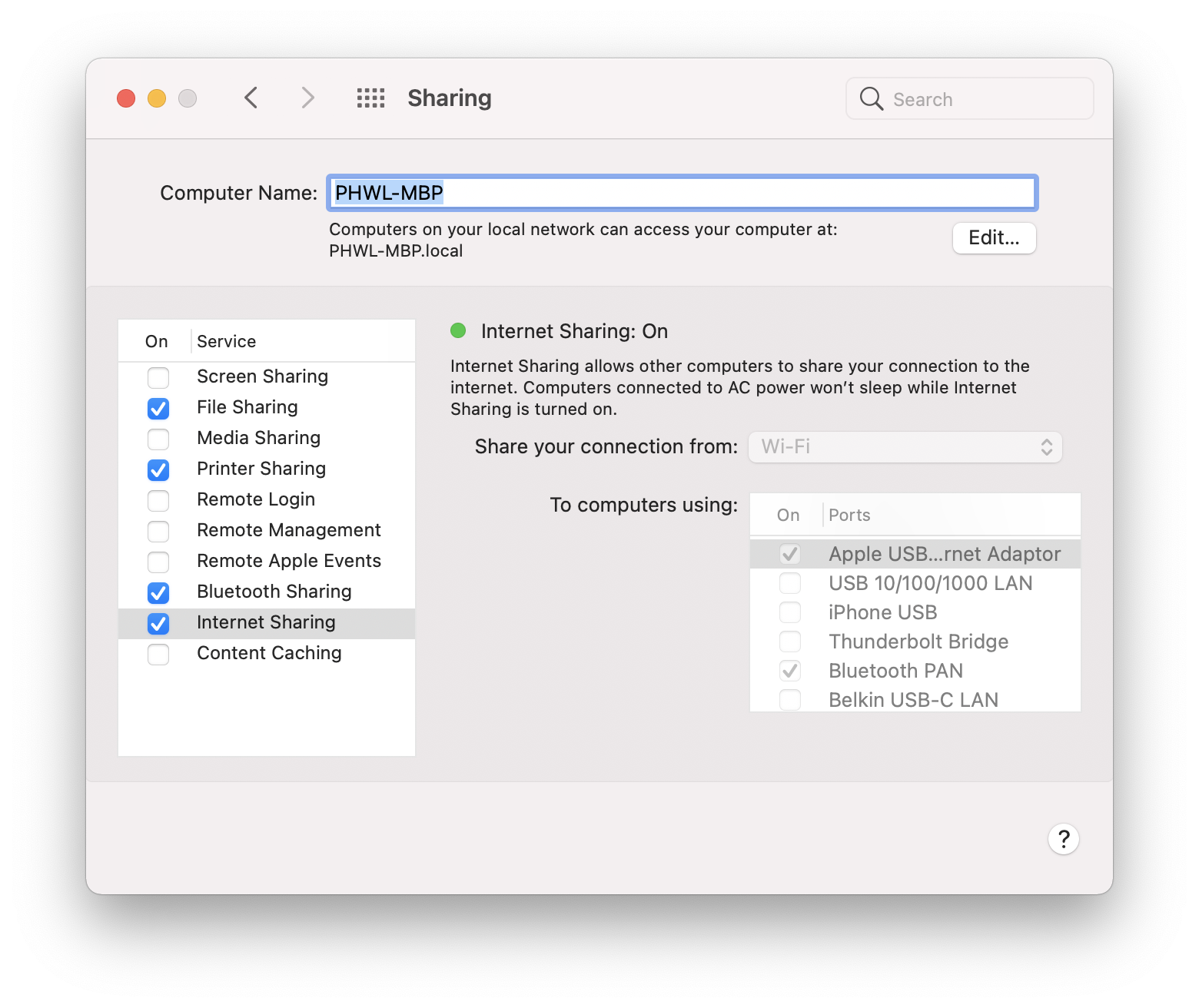
In “Control Panel” on your Mac, enable Internet sharing. On my machine the device is called “Apple USB Ethernet Adaptor” so you have to turn off the “Internet Sharing” service on the left, turn on the “Apple USB Ethernet Adaptor” and then turn on “Internet Sharing” to the the window below:
2.2. Windows 10
Connect your PC to the BBG using the microUSB. Connect your BBG Ethernet port to the PC’s Ethernet using an Ethernet cable (you may need an Ethernet adaptor for your PC).
Instructions are here:
- Right Click on the Windows start button, and you will see a menu pop up.
- From there, you need to click on Network Connections.
- Once you do so, you will be redirected to the network windows. From there, click on change adapter settings.
- Now, you will be redirected to the list of all the network connections available online.
- From there, right-click on your Wi-Fi adapter and then go to properties.
- Now you need to toggle the option “Allow other network users to connect.”
- Once done, then you need also to select the Ethernet port through which you want to allow the connection.
Also, make sure that you choose the right ethernet to share the internet. If you do not make the right choice, then your connection sharing will fail. This is specifically true for those who have VPN software installed as it can create virtual ethernet ports and list them there.
3. Checking Connection
After entering Return, you should see the login prompt.
Debian GNU/Linux 10 beaglebone ttyGS0

BeagleBoard.org Debian Buster IoT TIDL Image 2020-04-06

Support: http://elinux.org/Beagleboard:BeagleBoneBlack_Debian

default username:password is [debian:temppwd]

beaglebone login: debian
Password:
Last login: Fri Feb 26 05:04:59 UTC 2021 on ttyGS0

The programs included with the Debian GNU/Linux system are free software;
the exact distribution terms for each program are described in the
individual files in /usr/share/doc/*/copyright.

Debian GNU/Linux comes with ABSOLUTELY NO WARRANTY, to the extent
permitted by applicable law.
Then check if you can ping sydney.edu.au:
debian@beaglebone:~$ ping -c 3 sydney.edu.au
PING sydney.edu.au (129.78.5.8) 56(84) bytes of data.
64 bytes from svdns.sydney.edu.au (129.78.5.8): icmp_seq=1 ttl=242 time=12.1 ms
64 bytes from svdns.sydney.edu.au (129.78.5.8): icmp_seq=2 ttl=242 time=12.4 ms
64 bytes from svdns.sydney.edu.au (129.78.5.8): icmp_seq=3 ttl=242 time=19.8 ms

--- sydney.edu.au ping statistics ---
3 packets transmitted, 3 received, 0% packet loss, time 6ms
rtt min/avg/max/mdev = 12.144/14.812/19.849/3.566 ms
You can exit the screen program with control-A and then k (if you just disconnect the USB, the /dev/cu.usbmodemBBG2200804786 device will disappear and you will need to reboot the Mac if it is needed again).
3. To Login to the BBG via Ethernet
On the BeagleBone type:
debian@beaglebone:~$ ifconfig
eth0: flags=-28605<UP,BROADCAST,RUNNING,MULTICAST,DYNAMIC>  mtu 1500
        inet 169.254.120.60  netmask 255.255.0.0  broadcast 169.254.255.255
        inet6 fe80::1642:fcff:fe0c:b433  prefixlen 64  scopeid 0x20<link>
        ether 14:42:fc:0c:b4:33  txqueuelen 1000  (Ethernet)
        RX packets 719  bytes 229866 (224.4 KiB)
        RX errors 0  dropped 0  overruns 0  frame 0
        TX packets 331  bytes 91879 (89.7 KiB)
        TX errors 0  dropped 0 overruns 0  carrier 0  collisions 0
        device interrupt 45

lo: flags=73<UP,LOOPBACK,RUNNING>  mtu 65536
        inet 127.0.0.1  netmask 255.0.0.0
        inet6 ::1  prefixlen 128  scopeid 0x10<host>
        loop  txqueuelen 1000  (Local Loopback)
        RX packets 3968  bytes 266448 (260.2 KiB)
        RX errors 0  dropped 0  overruns 0  frame 0
        TX packets 3968  bytes 266448 (260.2 KiB)
        TX errors 0  dropped 0 overruns 0  carrier 0  collisions 0

usb0: flags=4163<UP,BROADCAST,RUNNING,MULTICAST>  mtu 1500
        inet 192.168.7.2  netmask 255.255.255.0  broadcast 192.168.7.255
        inet6 fe80::1642:fcff:fe0c:b435  prefixlen 64  scopeid 0x20<link>
        ether 14:42:fc:0c:b4:35  txqueuelen 1000  (Ethernet)
        RX packets 0  bytes 0 (0.0 B)
        RX errors 0  dropped 0  overruns 0  frame 0
        TX packets 0  bytes 0 (0.0 B)
        TX errors 0  dropped 0 overruns 0  carrier 0  collisions 0

usb1: flags=4099<UP,BROADCAST,MULTICAST>  mtu 1500
        inet 192.168.6.2  netmask 255.255.255.0  broadcast 192.168.6.255
        ether 14:42:fc:0c:b4:39  txqueuelen 1000  (Ethernet)
        RX packets 0  bytes 0 (0.0 B)
        RX errors 0  dropped 0  overruns 0  frame 0
        TX packets 0  bytes 0 (0.0 B)
        TX errors 0  dropped 0 overruns 0  carrier 0  collisions 0
The ifconfig command shows that the eth0 device has the IP address 169.254.120.60. You can use this address directly, or beaglebone.local if that is the only device on your local network.
From another terminal window on your Mac (or any other machine on the same network), you should be able to log into the BBG:
phwl@PHWL-MBP ~ % ssh [email protected] # or ssh [email protected]
The authenticity of host '169.254.120.60 (169.254.120.60)' can't be established.
ECDSA key fingerprint is SHA256:6iPvBW868tpt8HVZLemzVVPKAI5n5C669GwfLKiws34.
Are you sure you want to continue connecting (yes/no/[fingerprint])? yes
Warning: Permanently added '169.254.120.60' (ECDSA) to the list of known hosts.
Debian GNU/Linux 10

BeagleBoard.org Debian Buster IoT TIDL Image 2020-04-06

Support: http://elinux.org/Beagleboard:BeagleBoneBlack_Debian

default username:password is [debian:temppwd]

[email protected]'s password:

The programs included with the Debian GNU/Linux system are free software;
the exact distribution terms for each program are described in the
individual files in /usr/share/doc/*/copyright.

Debian GNU/Linux comes with ABSOLUTELY NO WARRANTY, to the extent
permitted by applicable law.
Last login: Fri Feb 26 05:05:45 2021
3. GPIO
Since Linux v4.8, the standard way of using Linux GPIO has been via libgpiod. Prior to the introduction of libgpiod, the sysfs interface was used, but sysfs is depreciated and was removed from the mainline Linux kernel in 2020. The best source of information on libgpiod comes with the library and the (libgpiod manual).
The library comes with a number of command line tools to manipulate GPIOs:
-
gpiodetect - list all gpiochips present on the system, their names, labels and number of GPIO lines
-
gpioinfo - list all lines of specified gpiochips, their names, consumers, direction, active state and additional flags
-
gpioget - read values of specified GPIO lines
-
gpioset - set values of specified GPIO lines, potentially keep the lines exported and wait until timeout, user input or signal
-
gpiofind - find the gpiochip name and line offset given the line name
-
gpiomon - wait for events on GPIO lines, specify which events to watch, how many events to process before exiting or if the events should be reported to the console.
Here are some usage examples from the Linux documentation (some like gpiomon won’t work on the BBG without an input source):
    # Read the value of a single GPIO line.
    $ gpioget gpiochip1 23
    0

    # Read two values at the same time. Set the active state of the lines
    # to low.
    $ gpioget --active-low gpiochip1 23 24
    1 1

    # Set values of two lines, then daemonize and wait for a signal (SIGINT or
    # SIGTERM) before releasing them.
    $ gpioset --mode=signal --background gpiochip1 23=1 24=0

    # Set the value of a single line, then exit immediately. This is useful
    # for floating pins.
    $ gpioset gpiochip1 23=1

    # Find a GPIO line by name.
    $ gpiofind "USR-LED-2" gpiochip1 23

    # Toggle a GPIO by name, then wait for the user to press ENTER.
    $ gpioset --mode=wait `gpiofind "USR-LED-2"`=1

    # Wait for three rising edge events on a single GPIO line, then exit.
    $ gpiomon --num-events=3 --rising-edge gpiochip2 3
    event:  RISING EDGE offset: 3 timestamp: [    1151.814356387]
    event:  RISING EDGE offset: 3 timestamp: [    1151.815449803]
    event:  RISING EDGE offset: 3 timestamp: [    1152.091556803]

    # Wait for a single falling edge event. Specify a custom output format.
    $ gpiomon --format="%e %o %s %n" --falling-edge gpiochip1 4 0 4 1156 615459801

    # Pause execution until a single event of any type occurs. Don't print
    # anything. Find the line by name.
    $ gpiomon --num-events=1 --silent `gpiofind "USR-IN"`

    # Monitor multiple lines, exit after the first event.
    $ gpiomon --silent --num-events=1 gpiochip0 2 3 5
1. Laboratory Experiment
Part 1 - Setup (10%)
To use GPIO on the BBG, one must first login to the beagleboard:
phwl@PHWL-MBP lab1-gpio % ssh [email protected]
Debian GNU/Linux 10

BeagleBoard.org Debian Buster IoT Image 2020-04-06

Support: http://elinux.org/Beagleboard:BeagleBoneBlack_Debian

default username:password is [debian:temppwd]

[email protected]'s password:

The programs included with the Debian GNU/Linux system are free software;
the exact distribution terms for each program are described in the
individual files in /usr/share/doc/*/copyright.

Debian GNU/Linux comes with ABSOLUTELY NO WARRANTY, to the extent
permitted by applicable law.
Last login: Wed Mar  3 04:58:05 2021 from 10.17.29.225
Then update the Debian package manager:
debian@beaglebone:~$ sudo apt update
[sudo] password for debian:
Hit:1 http://deb.debian.org/debian buster InRelease
Get:2 http://deb.debian.org/debian buster-updates InRelease [51.9 kB]
Get:3 http://repos.rcn-ee.com/debian buster InRelease [3,078 B]
Get:4 http://deb.debian.org/debian-security buster/updates InRelease [65.4 kB]
Get:5 http://deb.debian.org/debian-security buster/updates/main armhf Packages [262 kB]
Get:6 http://repos.rcn-ee.com/debian buster/main armhf Packages [1,740 kB]
Fetched 2,122 kB in 50s (42.6 kB/s)
Reading package lists... Done
Building dependency tree
Reading state information... Done
110 packages can be upgraded. Run 'apt list --upgradable' to see them.
Now install the libgpiod library and git:
debian@beaglebone:~$ sudo apt install libgpiod-dev git
Reading package lists... Done
Building dependency tree
Reading state information... Done
libgpiod-dev is already the newest version (1.4.1-2rcnee3~buster+20190906).
Suggested packages:
  gettext-base git-daemon-run | git-daemon-sysvinit git-doc git-el git-email
  git-gui gitk gitweb git-cvs git-mediawiki git-svn
The following packages will be upgraded:
  git
1 upgraded, 0 newly installed, 0 to remove and 109 not upgraded.
Need to get 4,542 kB of archives.
After this operation, 50.2 kB of additional disk space will be used.
Do you want to continue? [Y/n]
Get:1 http://deb.debian.org/debian buster/main armhf git armhf 1:2.20.1-2+deb10u3 [4,542 kB]
Fetched 4,542 kB in 3s (1,396 kB/s)
(Reading database ... 72582 files and directories currently installed.)
Preparing to unpack .../git_1%3a2.20.1-2+deb10u3_armhf.deb ...
Unpacking git (1:2.20.1-2+deb10u3) over (1:2.20.1-2+deb10u1) ...
Setting up git (1:2.20.1-2+deb10u3) ...
Clone the starting files for this lab
debian@beaglebone:~$ git clone https://github.com/phwl/elec3607-labquestions.git
Cloning into 'elec3607-labquestions'...
remote: Enumerating objects: 63, done.
remote: Counting objects: 100% (63/63), done.
remote: Compressing objects: 100% (39/39), done.
remote: Total 63 (delta 21), reused 52 (delta 13), pack-reused 0
Unpacking objects: 100% (63/63), done.
and install a Device Tree overlay to set the pinctl mode of the pins we will be using to Mode 7 (we will cover Device Trees later in this course):
debian@beaglebone:~$ cd elec3607-labquestions/labs/lab1-gpio/
debian@beaglebone:~/elec3607-labquestions/labs/lab1-gpio$ make install
sudo cp PHWL-GPIO-00A0.dtbo /lib/firmware
sudo cp uEnv.txt /boot
You will need to reboot the system for the Device Tree changes to take effect.
debian@beaglebone:~/elec3607-labquestions/labs/lab1-gpio$ sudo shutdown -r now
You can check everything is working by detecting the GPIO chips and printing their labels and state.
debian@beaglebone:~$ gpiodetect
gpiochip0 [gpio] (32 lines)
gpiochip1 [gpio] (32 lines)
gpiochip2 [gpio] (32 lines)
gpiochip3 [gpio] (32 lines)
debian@beaglebone:~$ gpioinfo
gpiochip0 - 32 lines:
	line   0:  "MDIO_DATA"       unused   input  active-high
	line   1:   "MDIO_CLK"       unused   input  active-high
...
Now turn on the D5 LED for 10 seconds using
debian@beaglebone:~$ gpioset -m time -s 10 gpiochip1 24=1
and turn it off for 10 seconds
debian@beaglebone:~$ gpioset -m time -s 10 gpiochip1 24=0
Note that after gpioset exits, the data of the output is undefined.
Part 2 - S2 Button Input (30%)
Download, compile and execute the blink program which flashes the D5 LED as follows
debian@beaglebone:~/elec3607-labquestions/labs/lab1-gpio$ ls
blink.c  Makefile  PHWL-GPIO-00A0.dtbo  PHWL-GPIO.dts  ssd.c
debian@beaglebone:~/elec3607-labquestions/labs/lab1-gpio$ make
cc    -c -o ssd.o ssd.c
gcc -o ssd ssd.c -lgpiod
cc    -c -o blink.o blink.c
gcc -o blink blink.c -lgpiod
dtc -O dtb -o PHWL-GPIO-00A0.dtbo -b 0 -@ PHWL-GPIO.dts
debian@beaglebone:~/elec3607-labquestions/labs/lab1-gpio$ ./blink
Here is a listing of blink.c
1
2
3
4
5
6
7
8
9
10
11
12
13
14
15
16
17
18
19
20
21
22
23
24
25
26
27
28
29
30
31
32
33
34
/*
 * **    blink.c -    blink with 1s delay
 * */

#include <stdio.h>
#include <unistd.h>
#include <gpiod.h>

#define GPIOCHIP        1
#define GPIOLINE        24

int
main(int argc, char *argv[])
{
        struct gpiod_chip *output_chip;
        struct gpiod_line *output_line;
        int line_value;

        /* open chip and get line */
        output_chip = gpiod_chip_open_by_number(GPIOCHIP);
        output_line = gpiod_chip_get_line(output_chip, GPIOLINE);

        /* config as output and set a description */
        gpiod_line_request_output(output_line, "blink", GPIOD_LINE_ACTIVE_STATE_HIGH);

        for (;;)
        {
                line_value = !line_value;
                gpiod_line_set_value(output_line, line_value);
                sleep(1);
        }

        return 0;
}
Referring to the libgpiod manual, we obtain a descriptor for the chip specified by GPIOCHIP in line 20. Using that descriptor we obtain one for the line in line 21.
In line 24, we configure the pin as an output, and give it the name “blink” (this is called a consumer in libgpiod). Line 28 toggles line_value between a true and false value, which is written to the line in line 29. We then sleep for 1 second before returning to the top of the infinite loop. You can press control-C to exit the program.
Modify the program so that, in addition to blinking the LED, it will print the status of the S2 button once a second as below.
debian@beaglebone:~$ ./blink
S2=1
...
S2=0
Part 3 - Seven Segment Display (60%)

Here is a listing of ssd.c, a program to be completed in this exercise.
1
2
3
4
5
6
7
8
9
10
11
12
13
14
15
16
17
18
19
20
21
22
23
24
25
26
27
28
29
30
31
32
33
34
35
36
37
38
39
40
41
42
43
44
45
46
47
48
49
50
51
52
53
54
55
56
57
58
59
60
61
62
63
64
65
66
67
68
69
70
71
72
73
/*
 * ssd.c -    count up and down on the SSD
 *
*/

#include <stdio.h>
#include <unistd.h>
#include <gpiod.h>

/* the SSD is entirely on this chip */
#define OUT_GPIOCHIP	0

/* the S2 button on the BBG */
#define	IN_GPIOCHIP		2
#define	IN_GPIOLINE		8

#define	NELTS(x)	(sizeof(x) / sizeof(x[0]))	// calculate number of elements in x
#define	SEGMENTS	NELTS(gpiossd)

static int	gpiossd[] = { 2, 13, 12, 4, 5, 15, 31 };

/* FILL THIS IN */
static int	ssd[][SEGMENTS] = {
	{ 1, 1, 1, 1, 1, 1, 0 },	/* 0 */
	{ 0, 0, 0, 0, 0, 0, 0 },	/* 1 */
	{ 0, 0, 0, 0, 0, 0, 0 },	/* 2 */
	{ 0, 0, 0, 0, 0, 0, 0 },	/* 3 */
	{ 0, 0, 0, 0, 0, 0, 0 },	/* 4 */
	{ 0, 0, 0, 0, 0, 0, 0 },	/* 5 */
	{ 0, 0, 0, 0, 0, 0, 0 },	/* 6 */
	{ 0, 0, 0, 0, 0, 0, 0 },	/* 7 */
	{ 0, 0, 0, 0, 0, 0, 0 },	/* 8 */
	{ 0, 0, 0, 0, 0, 0, 0 } };	/* 9 */

int
main(int argc, char *argv[])
{
    struct	gpiod_chip *output_chip;
    struct	gpiod_line *output_line[SEGMENTS];
	struct	gpiod_chip *input_chip;
	struct	gpiod_line *input_line;
    int		line_value;
	int		i, j;

	/* open input */
	input_chip = gpiod_chip_open_by_number(IN_GPIOCHIP);
	input_line = gpiod_chip_get_line(input_chip, IN_GPIOLINE);
	gpiod_line_request_input(input_line, "ssd");

    /* open /dev/gpiochip0 */
    output_chip = gpiod_chip_open_by_number(OUT_GPIOCHIP);
	for (i = 0; i < SEGMENTS; i++)
	{
		output_line[i] = gpiod_chip_get_line(output_chip, gpiossd[i]);
		/* config as output and set a description */
		gpiod_line_request_output(output_line[i], "ssd", GPIOD_LINE_ACTIVE_STATE_HIGH);
	}

	int d = 0;		/* the digit to display */
	for (;;)
	{
		/* display all segments */
		for (j = 0; j < SEGMENTS; j++)
		{
            /* FILL THIS IN */
		}
        	sleep(1);
		/* update count */

        /* FILL THIS IN */
	}
    return 0;
}
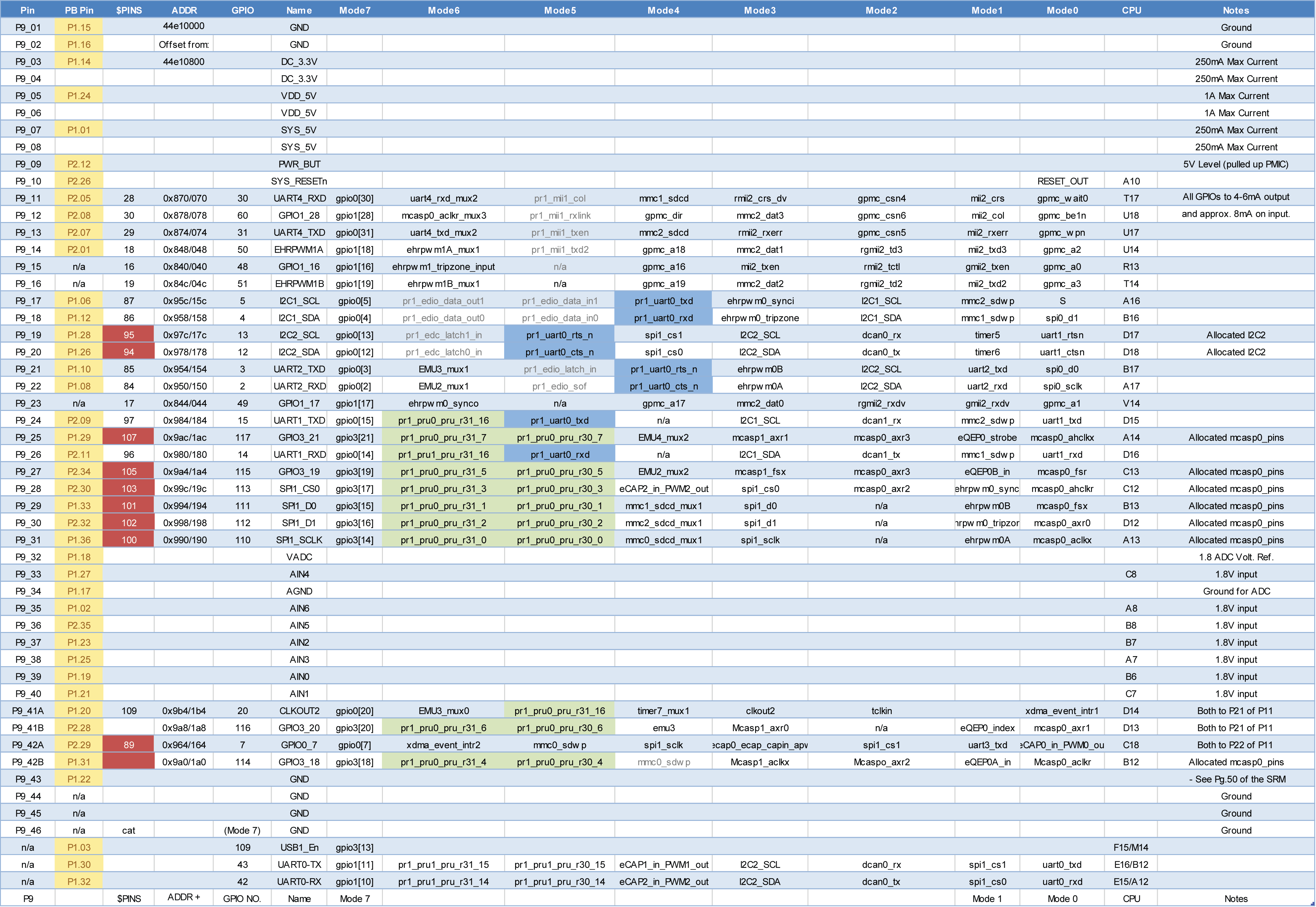
Refer to the Beaglebone P9 connector table for the mapping of pins to the gpiochip0 lines.
The data sheet for a seven segment display (SSD) is available here.
- Calculate the resistor value so that the current to drive the LED (voltage is 3.3V-Vf where Vf=the diode forward voltage drop) doesn’t exceed 4mA.
- After studying
ssd.c, connect up the SSD to the BBG via a breadboard. - Complete the “FILL THIS IN” parts of
ssd.cso the value changes in value 0 to 9 every second then goes back to 0. When S2 is pressed it should count backwards.
Note that for the program to work, you will need to use the same GPIO lines as the program.
4. Device Tree
This section describes configuration of the BeagleBone Green GPIO pinmux settings via the Linux Device Tree.
1. Setting pinmux values via the Device Tree
The pins of the BBG P9 header have different operations depending on the pinmum mode chosen. Looking at the P9 header, Mode 7 connects the GPIO line to the pin of the AM335X chip. To configure this, we need to set the mode via the Linux Device Tree (DT). How the DT works will be covered as a later topic, but this (admittedly complicated) configuration below will set
First make the following dts file:
$ cat PHWL-GPIO.dts
/*
* Copyright (C) 2012 Texas Instruments Incorporated - http://www.ti.com/
*
* This program is free software; you can redistribute it and/or modify
* it under the terms of the GNU General Purpose License Version 2 as
* published by the Free Software Foundation
*
* Original from: github.com/jadonk/validation-scripts/blob/master/test-capemgr/
*
* Modified by Derek Molloy for the example on www.derekmolloy.ie
* that maps GPIO pins for the example
*
* Modified by Philip Leong for SSD exercise
*
*/

/dts-v1/;
/plugin/;

/{
       compatible = "ti,beaglebone", "ti,beaglebone-black";
       part-number = "PHWL-GPIO";
       version = "00A0";

       fragment@0 {
             target = <&am33xx_pinmux>;

             __overlay__ {
                  pinctrl_test: PHWL_GPIO_Pins {
			pinctrl-single,pins = <

                   0x180 0x07  /* P9_26 OUT */
                   0x184 0x07  /* P9_24 OUT */
                   0x150 0x07  /* P9_22 OUT */
                   0x178 0x07  /* P9_20 OUT */
                   0x17c 0x07  /* P9_19 OUT */
                   0x158 0x07  /* P9_18 OUT */
                   0x15c 0x07  /* P9_17 OUT */
                   0x074 0x07  /* P9_13 OUT */
                   0x0a8 0x37  /* P8_43 PULLUP IN */

                   /* OUTPUT  GPIO(mode7) 0x07 pulldown, 0x17 pullup, 0x?f no pullup/down */
                   /* INPUT   GPIO(mode7) 0x27 pulldown, 0x37 pullup, 0x?f no pullup/down */

			>;
		  };
             };
       };

       fragment@1 {
		target = <&ocp>;
		__overlay__ {
			test_helper: helper {
				compatible = "bone-pinmux-helper";
				pinctrl-names = "default";
				pinctrl-0 = <&pinctrl_test>;
				status = "okay";
			};
		};
	};
};
to build
$ dtc -O dtb -o PHWL-GPIO-00A0.dtbo -b 0 -@ PHWL-GPIO.dts
$ sudo cp PHWL-GPIO-00A0.dtbo /lib/firmware/
Modify /boot/uEnv.txt to be:
$ cat /boot/uEnv.txt
#Docs: http://elinux.org/Beagleboard:U-boot_partitioning_layout_2.0

uname_r=4.14.108-ti-r131
#uuid=
#dtb=
cmdline=coherent_pool=1M net.ifnames=0 rng_core.default_quality=100 quiet
enable_uboot_overlays=1
uboot_overlay_addr0=/lib/firmware/PHWL-GPIO-00A0.dtbo

#In the event of edid real failures, uncomment this next line:
#cmdline=coherent_pool=1M net.ifnames=0 rng_core.default_quality=100 quiet video=HDMI-A-1:1024x768@60e

##enable x15: eMMC Flasher:
##make sure, these tools are installed: dosfstools rsync
#cmdline=init=/opt/scripts/tools/eMMC/init-eMMC-flasher-v3-no-eeprom.sh
reboot (shutdown -r now) and the modes should have changed to 007
$ grep 007 /sys/kernel/debug/pinctrl/44e10800.pinmux/pins
pin 21 (PIN21) 44e10854 00000007 pinctrl-single
pin 23 (PIN23) 44e1085c 00000007 pinctrl-single
pin 29 (PIN29) 44e10874 00000007 pinctrl-single
pin 84 (PIN84) 44e10950 00000007 pinctrl-single
pin 85 (PIN85) 44e10954 00000007 pinctrl-single
pin 86 (PIN86) 44e10958 00000007 pinctrl-single
pin 87 (PIN87) 44e1095c 00000007 pinctrl-single
pin 94 (PIN94) 44e10978 00000007 pinctrl-single
pin 95 (PIN95) 44e1097c 00000007 pinctrl-single
5. Si5351 interface via i2c
This section describes how to connect the BeagleBone to a Silicon Labs Si5351 i2c clock generator.
1. I2C Interface to Si5351
The i2c interface is simple, ensure that the SDA and SCL lines of the Si5351 are connected to an appropriate port on the Beaglebone. In the example below, I used /dev/i2c-2.
Then make sure all the software required is installed on the BBG.
sudo apt update
sudo apt-get install libi2c-dev
The commands below show all the i2c devices and that the Si5351 at address 0x60 is responding to the probe on I2C2 (i2c chip 2):
debian@beaglebone:~$ i2cdetect -l
i2c-1	i2c       	OMAP I2C adapter                	I2C adapter
i2c-2	i2c       	OMAP I2C adapter                	I2C adapter
i2c-0	i2c       	OMAP I2C adapter                	I2C adapter
debian@beaglebone:~$ i2cdetect -y -r 2
     0  1  2  3  4  5  6  7  8  9  a  b  c  d  e  f
00:          -- -- -- -- -- -- -- -- -- -- -- -- --
10: -- -- -- -- -- -- -- -- -- -- -- -- -- -- -- --
20: -- -- -- -- -- -- -- -- -- -- -- -- -- -- -- --
30: -- -- -- -- -- -- -- -- -- -- -- -- -- -- -- --
40: -- -- -- -- -- -- -- -- -- -- -- -- -- -- -- --
50: -- -- -- -- -- -- -- -- -- -- -- -- -- -- -- --
60: 60 -- -- -- -- -- -- -- -- -- -- -- -- -- -- --
70: -- -- -- -- -- -- -- --
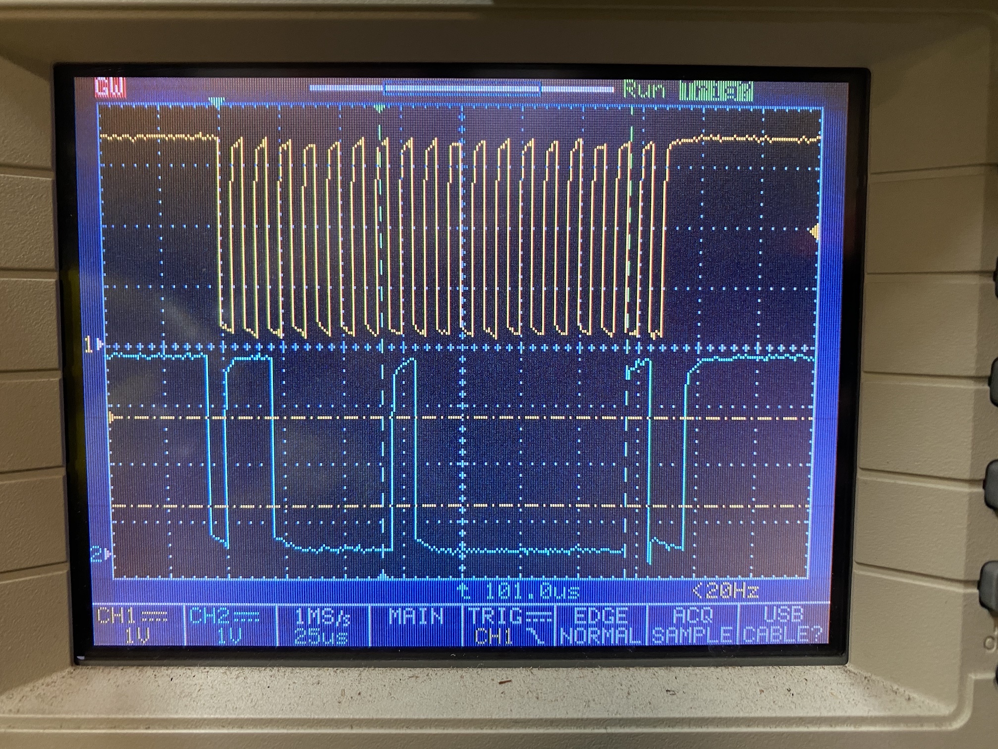
Here is part of the i2c transaction for i2cdetect -y -r 2 0x60 0x60.
2. Linux userspace driver
There are several ways that this interface can be made. We are going to create a userspace driver with the Linux i2c-dev module (which is the most straightforward approach). The following program, derived from the Linux Kernel userspace driver documentation reads and prints register 0 of device /dev/i2c-2, address 0x60, i.e. register 0 of the Si5351. Note that the reason we need to specify address 0x60 is that there could be multiple devices connected to a single i2c chip.
1
2
3
4
5
6
7
8
9
10
11
12
13
14
15
16
17
18
19
20
21
22
23
24
25
26
27
28
29
30
31
32
33
34
35
36
37
38
39
40
41
#include <stdio.h>
#include <stdlib.h>
#include <fcntl.h>
#include <sys/ioctl.h>
#include <linux/i2c-dev.h>
#include <i2c/smbus.h>

#define	I2C_FNAME	"/dev/i2c-2"
#define	SI5351_ADDR	0x60

int	i2c_file;

void i2c_init()
{
	i2c_file = open(I2C_FNAME, O_RDWR);
	if (i2c_file < 0)
		exit(1);
}

int i2c_read(unsigned char reg)
{
	if (ioctl(i2c_file, I2C_SLAVE, SI5351_ADDR) < 0)
		exit(1);

	int res;

	/* Using SMBus commands */
	res = i2c_smbus_read_byte_data(i2c_file, reg);
	if (res < 0)
		exit(1);
	else
		printf("r dev(0x%x) reg(0x%x)=0x%x\n", SI5351_ADDR, reg, res);
	return res;
}

int
main()
{
	i2c_init();
	i2c_read(0);
}
It can be compiled and executed as follows:
debian@beaglebone:~$ gcc -o si5351 si5351.c -li2c
debian@beaglebone:~$ ./si5351
r dev(0x60) reg(0x0)=0x11
3. Programming the Clock Generator
The data sheet for the Si5351 refers to the Clock builder software. This is only available for Windows but in embedded systems it is a fact of life that if you use operating system X, there will be a piece of software that is only supported on operating system Y that you need. Here is a header file that I generated for CLK0 and CLK1 outputs of 28.1544 MHz.
1
2
3
4
5
6
7
8
9
10
11
12
13
14
15
16
17
18
19
20
21
22
23
24
25
26
27
28
29
30
31
32
33
34
35
36
37
38
39
40
41
42
43
44
45
46
47
48
49
50
51
52
53
54
55
56
57
58
59
60
61
62
63
64
65
66
67
68
69
70
71
72
73
74
75
76
77
78
79
80
81
82
83
84
85
86
87
88
89
90
91
92
93
94
95
96
97
98
99
100
101
102
103
104
105
106
107
108
109
110
111
112
113
114
115
116
117
118
119
120
121
122
123
124
125
126
127
128
129
130
131
132
133
134
135
136
137
138
139
140
141
142
143
144
145
146
147
148
149
150
151
152
153
154
155
156
157
158
159
160
161
162
163
164
165
166
167
168
169
170
171
172
173
174
175
176
177
178
179
180
181
182
183
184
185
186
187
188
189
190
191
192
193
194
195
196
197
198
199
200
201
202
203
204
205
206
207
208
209
210
211
212
213
214
215
216
217
218
219
220
221
222
223
224
225
226
227
228
229
230
231
232
233
234
235
236
237
238
239
240
/*
 * Si5351A Rev B Configuration Register Export Header File
 *
 * This file represents a series of Silicon Labs Si5351A Rev B
 * register writes that can be performed to load a single configuration
 * on a device. It was created by a Silicon Labs ClockBuilder Pro
 * export tool.
 *
 * Part:		                                       Si5351A Rev B
 * Design ID:
 * Includes Pre/Post Download Control Register Writes: Yes
 * Created By:                                         ClockBuilder Pro v3.1 [2021-01-18]
 * Timestamp:                                          2021-03-12 15:00:15 GMT-08:00
 *
 * A complete design report corresponding to this export is included at the end
 * of this header file.
 *
 */

#ifndef SI5351A_REVB_REG_CONFIG_HEADER
#define SI5351A_REVB_REG_CONFIG_HEADER

#define SI5351A_REVB_REG_CONFIG_NUM_REGS				52

typedef struct
{
	unsigned int address; /* 16-bit register address */
	unsigned char value; /* 8-bit register data */

} si5351a_revb_register_t;

si5351a_revb_register_t const si5351a_revb_registers[SI5351A_REVB_REG_CONFIG_NUM_REGS] =
{
	{ 0x0002, 0x53 },
	{ 0x0003, 0x00 },
	{ 0x0004, 0x20 },
	{ 0x0007, 0x00 },
	{ 0x000F, 0x00 },
	{ 0x0010, 0x0F },
	{ 0x0011, 0x0F },
	{ 0x0012, 0x8C },
	{ 0x0013, 0x8C },
	{ 0x0014, 0x8C },
	{ 0x0015, 0x8C },
	{ 0x0016, 0x8C },
	{ 0x0017, 0x8C },
	{ 0x001A, 0xAF },
	{ 0x001B, 0xC8 },
	{ 0x001C, 0x00 },
	{ 0x001D, 0x0E },
	{ 0x001E, 0x8D },
	{ 0x001F, 0x00 },
	{ 0x0020, 0x85 },
	{ 0x0021, 0x58 },
	{ 0x002A, 0x00 },
	{ 0x002B, 0x04 },
	{ 0x002C, 0x00 },
	{ 0x002D, 0x0D },
	{ 0x002E, 0xE0 },
	{ 0x002F, 0x00 },
	{ 0x0030, 0x00 },
	{ 0x0031, 0x00 },
	{ 0x0032, 0x00 },
	{ 0x0033, 0x04 },
	{ 0x0034, 0x00 },
	{ 0x0035, 0x0D },
	{ 0x0036, 0xE0 },
	{ 0x0037, 0x00 },
	{ 0x0038, 0x00 },
	{ 0x0039, 0x00 },
	{ 0x005A, 0x00 },
	{ 0x005B, 0x00 },
	{ 0x0095, 0x00 },
	{ 0x0096, 0x00 },
	{ 0x0097, 0x00 },
	{ 0x0098, 0x00 },
	{ 0x0099, 0x00 },
	{ 0x009A, 0x00 },
	{ 0x009B, 0x00 },
	{ 0x00A2, 0x00 },
	{ 0x00A3, 0x00 },
	{ 0x00A4, 0x00 },
	{ 0x00A5, 0x00 },
	{ 0x00A6, 0x00 },
	{ 0x00B7, 0x92 },

};

/*
 * Design Report
 *
 * Overview
 * ========
 * Part:               Si5351A
 * Created By:         ClockBuilder Pro v3.1 [2021-01-18]
 * Timestamp:          2021-03-12 15:00:15 GMT-08:00
 *
 * Design Notes
 * ============
 * Si5351A 10-pin MSOP
 *
 * Design Rule Check
 * =================
 * Errors:
 * - No errors
 *
 * Warnings:
 * - No warnings
 *
 * Design
 * ======
 * Inputs:
 *     IN0: 27 MHz
 *
 * Outputs:
 *    OUT0: 28.1544 MHz
 *          Enabled LVCMOS 8 mA
 *          Offset 0.000 s
 *    OUT1: 28.1544 MHz
 *          Enabled LVCMOS 8 mA
 *          Offset 0.000 s
 *    OUT2: Unused
 *
 * Frequency Plan
 * ==============
 * PLL_A:
 *    Enabled Features = None
 *    Fvco             = 893.9022 MHz
 *    M                = 33.1074888888888888... [ 33 + 4837/45000 ]
 *    Input0:
 *       Source           = Crystal
 *       Source Frequency = 27 MHz
 *       Fpfd             = 27 MHz
 *       Load Capacitance = Load_08pF
 *    Output0:
 *       Features       = None
 *       Disabled State = StopLow
 *       R              = 1  (2^0)
 *       Fout           = 28.1544 MHz
 *       N              = 31.75
 *    Output1:
 *       Features       = None
 *       Disabled State = StopLow
 *       R              = 1  (2^0)
 *       Fout           = 28.1544 MHz
 *       N              = 31.75
 *
 * Settings
 * ========
 *
 * Location      Setting Name    Decimal Value      Hex Value
 * ------------  --------------  -----------------  -----------------
 * 0x0002[3]     XO_LOS_MASK     0                  0x0
 * 0x0002[4]     CLK_LOS_MASK    1                  0x1
 * 0x0002[5]     LOL_A_MASK      0                  0x0
 * 0x0002[6]     LOL_B_MASK      1                  0x1
 * 0x0002[7]     SYS_INIT_MASK   0                  0x0
 * 0x0003[7:0]   CLK_OEB         0                  0x00
 * 0x0004[4]     DIS_RESET_LOLA  0                  0x0
 * 0x0004[5]     DIS_RESET_LOLB  1                  0x1
 * 0x0007[7:4]   I2C_ADDR_CTRL   0                  0x0
 * 0x000F[2]     PLLA_SRC        0                  0x0
 * 0x000F[3]     PLLB_SRC        0                  0x0
 * 0x000F[4]     PLLA_INSELB     0                  0x0
 * 0x000F[5]     PLLB_INSELB     0                  0x0
 * 0x000F[7:6]   CLKIN_DIV       0                  0x0
 * 0x0010[1:0]   CLK0_IDRV       3                  0x3
 * 0x0010[3:2]   CLK0_SRC        3                  0x3
 * 0x0010[4]     CLK0_INV        0                  0x0
 * 0x0010[5]     MS0_SRC         0                  0x0
 * 0x0010[6]     MS0_INT         0                  0x0
 * 0x0010[7]     CLK0_PDN        0                  0x0
 * 0x0011[1:0]   CLK1_IDRV       3                  0x3
 * 0x0011[3:2]   CLK1_SRC        3                  0x3
 * 0x0011[4]     CLK1_INV        0                  0x0
 * 0x0011[5]     MS1_SRC         0                  0x0
 * 0x0011[6]     MS1_INT         0                  0x0
 * 0x0011[7]     CLK1_PDN        0                  0x0
 * 0x0012[1:0]   CLK2_IDRV       0                  0x0
 * 0x0012[3:2]   CLK2_SRC        3                  0x3
 * 0x0012[4]     CLK2_INV        0                  0x0
 * 0x0012[5]     MS2_SRC         0                  0x0
 * 0x0012[6]     MS2_INT         0                  0x0
 * 0x0012[7]     CLK2_PDN        1                  0x1
 * 0x0013[1:0]   CLK3_IDRV       0                  0x0
 * 0x0013[3:2]   CLK3_SRC        3                  0x3
 * 0x0013[4]     CLK3_INV        0                  0x0
 * 0x0013[5]     MS3_SRC         0                  0x0
 * 0x0013[6]     MS3_INT         0                  0x0
 * 0x0013[7]     CLK3_PDN        1                  0x1
 * 0x0014[1:0]   CLK4_IDRV       0                  0x0
 * 0x0014[3:2]   CLK4_SRC        3                  0x3
 * 0x0014[4]     CLK4_INV        0                  0x0
 * 0x0014[5]     MS4_SRC         0                  0x0
 * 0x0014[6]     MS4_INT         0                  0x0
 * 0x0014[7]     CLK4_PDN        1                  0x1
 * 0x0015[1:0]   CLK5_IDRV       0                  0x0
 * 0x0015[3:2]   CLK5_SRC        3                  0x3
 * 0x0015[4]     CLK5_INV        0                  0x0
 * 0x0015[5]     MS5_SRC         0                  0x0
 * 0x0015[6]     MS5_INT         0                  0x0
 * 0x0015[7]     CLK5_PDN        1                  0x1
 * 0x0016[1:0]   CLK6_IDRV       0                  0x0
 * 0x0016[3:2]   CLK6_SRC        3                  0x3
 * 0x0016[4]     CLK6_INV        0                  0x0
 * 0x0016[5]     MS6_SRC         0                  0x0
 * 0x0016[6]     FBA_INT         0                  0x0
 * 0x0016[7]     CLK6_PDN        1                  0x1
 * 0x0017[1:0]   CLK7_IDRV       0                  0x0
 * 0x0017[3:2]   CLK7_SRC        3                  0x3
 * 0x0017[4]     CLK7_INV        0                  0x0
 * 0x0017[5]     MS7_SRC         0                  0x0
 * 0x0017[6]     FBB_INT         0                  0x0
 * 0x0017[7]     CLK7_PDN        1                  0x1
 * 0x001C[17:0]  MSNA_P1         3725               0x00E8D
 * 0x001F[19:0]  MSNA_P2         34136              0x08558
 * 0x001F[23:4]  MSNA_P3         45000              0x0AFC8
 * 0x002C[17:0]  MS0_P1          3552               0x00DE0
 * 0x002F[19:0]  MS0_P2          0                  0x00000
 * 0x002F[23:4]  MS0_P4          4                  0x00004
 * 0x0034[17:0]  MS1_P1          3552               0x00DE0
 * 0x0037[19:0]  MS1_P2          0                  0x00000
 * 0x0037[23:4]  MS1_P4          4                  0x00004
 * 0x005A[7:0]   MS6_P2          0                  0x00
 * 0x005B[7:0]   MS7_P2          0                  0x00
 * 0x0095[14:0]  SSDN_P2         0                  0x0000
 * 0x0095[7]     SSC_EN          0                  0x0
 * 0x0097[14:0]  SSDN_P3         0                  0x0000
 * 0x0097[7]     SSC_MODE        0                  0x0
 * 0x0099[11:0]  SSDN_P1         0                  0x000
 * 0x009A[15:4]  SSUDP           0                  0x000
 * 0x00A2[21:0]  VCXO_PARAM      0                  0x000000
 * 0x00A5[7:0]   CLK0_PHOFF      0                  0x00
 * 0x00A6[7:0]   CLK1_PHOFF      0                  0x00
 * 0x00B7[7:6]   XTAL_CL         2                  0x2
 *
 *
 */

#endif
Our approach will be to use the header file above as well as the information from Application Note AN619. The programming procedure is described in Figure 10 of the data sheet, summarised below.
ClockBuilder Desktop allows a user to generate RAM configuration files to program the Si5351 with custom frequency plans via I2C.  Once the register map has been generated, use the procedure below to program the device.

1. Disable all outputs.
       reg3 = 0xFF
2. Power down all output drivers
       reg 16 = 0x80*
       reg 17 = 0x80*
       reg 18 = 0x80*
       reg 19 = 0x80*
       reg 20 = 0x80*
       reg 21 = 0x80*
       reg 22 = 0x80*
       reg 23 = 0x80*
       * If using the Si5351C with no crystal present on XA/XB, set reg16-23 = 0x84.
3. Set interrupt maks register (see Register 2 description in datasheet)
4. If needed, set crystal load capacitance, XTAL_CL in reg183[7:6].  See datasheet for register description.
5. Write registers 15-92 and 149-170 using the contents of register map generated by ClockBuilder Desktop.
6. Apply PLL A and PLL B soft reset.
       reg177 = 0xAC
7. Enable outputs with OEB control in register 3.
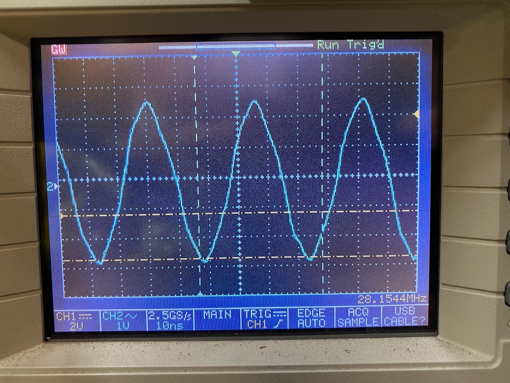
If these steps are followed, the output as specified in the include file should appear. It doesn’t look much like a square wave on my 150 MHz bandwidth oscilloscope. Why?
Finally, we wish to have the inphase (I) clock (CLK0) lagging the quadrature (Q) clock (CLK1) by 90 degrees (or 1/4 cycle). We can do this by setting the CLK1_PHOFF register to the appropriate value.
4. Laboratory Experiment
Update the lab files as below.
debian@beaglebone:~$ cd elec3607-labquestions/
debian@beaglebone:~/elec3607-labquestions$ git pull
remote: Enumerating objects: 18, done.
remote: Counting objects: 100% (18/18), done.
remote: Compressing objects: 100% (12/12), done.
remote: Total 14 (delta 2), reused 14 (delta 2), pack-reused 0
Unpacking objects: 100% (14/14), done.
From https://github.com/phwl/elec3607-labquestions
   6bf3a34..7c881d4  main       -> origin/main
Updating 6bf3a34..7c881d4
Fast-forward
 .DS_Store                                          | Bin 6148 -> 6148 bytes
 labs/.DS_Store                                     | Bin 0 -> 8196 bytes
 ... - GPIO_ ELEC3607 ELEC9607 Embedded Systems.pdf | Bin 0 -> 297484 bytes
 ...ruction_ ELEC3607 ELEC9607 Embedded Systems.pdf | Bin 0 -> 156733 bytes
 ...nerator_ ELEC3607 ELEC9607 Embedded Systems.pdf | Bin 0 -> 2310302 bytes
 labs/lab3-i2c/Makefile                             |   7 +
 labs/lab3-i2c/Si5351A-RevB-Registers.h             | 240 +++++++++++++++++++++
 labs/lab3-i2c/si5351.c                             |  41 ++++
 8 files changed, 288 insertions(+)
 create mode 100644 labs/.DS_Store
 create mode 100644 labs/lab1-gpio/Lab 1 - GPIO_ ELEC3607 ELEC9607 Embedded Systems.pdf
 create mode 100644 labs/lab2-sdrconstruction/Lab 2 - SDR Construction_ ELEC3607 ELEC9607 Embedded Systems.pdf
 create mode 100644 labs/lab3-i2c/Lab 3 - Si5351 Clock Generator_ ELEC3607 ELEC9607 Embedded Systems.pdf
 create mode 100644 labs/lab3-i2c/Makefile
 create mode 100755 labs/lab3-i2c/Si5351A-RevB-Registers.h
 create mode 100644 labs/lab3-i2c/si5351.c
debian@beaglebone:~/elec3607-labquestions$ cd labs/lab3-i2c/
debian@beaglebone:~/elec3607-labquestions/labs/lab3-i2c$
Part 1 - I2C Interface (30%)
Connect up your BBG to the Si5351. Verify that you can obtain the following output.
debian@beaglebone:~$ i2cdetect -y -r 2
     0  1  2  3  4  5  6  7  8  9  a  b  c  d  e  f
00:          -- -- -- -- -- -- -- -- -- -- -- -- --
10: -- -- -- -- -- -- -- -- -- -- -- -- -- -- -- --
20: -- -- -- -- -- -- -- -- -- -- -- -- -- -- -- --
30: -- -- -- -- -- -- -- -- -- -- -- -- -- -- -- --
40: -- -- -- -- -- -- -- -- -- -- -- -- -- -- -- --
50: -- -- -- -- -- -- -- -- -- -- -- -- -- -- -- --
60: 60 -- -- -- -- -- -- -- -- -- -- -- -- -- -- --
70: -- -- -- -- -- -- -- --
Part 2 - I2C Transaction (30%)
Use the userspace i2c driver (si5351.c) shown above to read register 0.
Execute the program and capture the activity of the SCL and SDA pins on an oscilloscope. Make a printout of the oscilloscope display and annotate all parts of
the i2c transaction (start, data, r/w, ack, etc). What is the period of the entire transaction?
Part 3 - Si5351 Configuration (40%)
Modify the userspace driver for the Si5351 to generate a 7 MHz square wave output on CLK0 and CLK1, with CLK1 being delayed by 90 degrees from CLK0.
6. Cross-compiling Kernel
This section describes how to cross compile the Beaglebone Black (BBB) or Beaglebone Green (BBG) Linux kernel on an Ubuntu 18.04 Linux machine.
1. Introduction
Before you proceed, back up your BBB files as we are going to overwrite them!
Although it is possible to develop directly on a Linux embedded
platform, often the machine speed, disk and memory capacity are insufficient for
doing kernel work. Moreover, not all embedded systems have luxuries
such as Ethernet. For these reasons, the normal practice is to
compile on a more powerful host machine. In the descriptions that following, the $ prompt is from the host machine and the debian@beaglebone:~$ prompt is on the BBB.
The system that I am using is Ubuntu 18.04.5. Start by installing this on your real or virtual machine.
Also, you should update the Debian distribution on your BBB. Download and flash the latest image. Boot from an SD card with the latest image by pressing the “User Boot” button while applying power.
Then extend the partition to the same size as the SDcard (the initial partition is 4 GB) by executing.
$ sudo /opt/scripts/tools/grow_partition.sh
and rebooting.
2. Reflash the eMMC
If you want to reflash the eMMC as well, uncomment the following line in /boot/uEnv.txt:
cmdline=init=/opt/scripts/tools/eMMC/init-eMMC-flasher-v3.sh
Then reboot again from the SDcard. After a few tens of seconds, you should see a pattern of the blue LEDs turning on in sequence. After tens of minutes, they will all turn off and your eMMC will have the same image as the SDcard.
2. Cross Compilation
On the BBB, work out what kernel version is being used:
debian@beaglebone:~$ uname -r
4.19.94-ti-r42
Now install the cross compiler.
$ sudo apt-get install gcc-arm-linux-gnueabi bison flex libssl-dev lzop u-boot-tools
Clone the BBB Linux repository and checkout the kernel version you are using. Even if you are planning to upgrade the kernel, it is a good idea to make sure you can rebuild the original one first.
$ git clone git://github.com/beagleboard/linux.git
$ git checkout 4.19.94-ti-r42
This installs installs the initial .config file for the BB kernel and tells the make system to use the cross compiler that we installed..
$ make ARCH=arm CROSS_COMPILE=arm-linux-gnueabi- bb.org_defconfig
You can configure the kernel with custom options using the command.
$ make ARCH=arm CROSS_COMPILE=arm-linux-gnueabi- menuconfig
While you are there, select the SiLabs 5351A/B/C driver under “Kernel Configuration > Device Drivers > Common Clock Framework” as illustrated below.
.config - Linux/arm 4.19.94 Kernel Configuration
 > Device Drivers > Common Clock Framework
  ┌─sssssssssssssssssssssss Common Clock Framework ─                        ┐
  │  Arrow keys navigate the menu.  <Enter> selects submenus ---> (or empty │
  │  submenus ----).  Highlighted letters are hotkeys.  Pressing <Y>        │
  │  includes, <N> excludes, <M> modularizes features.  Press <Esc><Esc> to │
  │  exit, <?> for Help, </> for Search.  Legend: [*] built-in  [ ]         │
  │ ┌─                                                                    ┐ │
  │ │    [ ] PLL Driver for HSDK platform                                 │ │
  │ │    < > Maxim 9485 Programmable Clock Generator                      │ │
  │ │    <*> Clock driver for SiLabs 5351A/B/C                            │ │
  │ │    < > Clock driver for SiLabs 514 devices                          │ │
  │ │    < > Clock driver for SiLabs 544 devices                          │ │
  │ │    < > Clock driver for SiLabs 570 and compatible devices           │ │
  │ │    < > Clock driver for TI CDCE706 clock synthesizer                │ │
  │ │    < > Clock driver for TI CDCE913/925/937/949 devices              │ │
  │ │    < > Clock driver for CS2000 Fractional-N Clock Synthesizer & Cloc│ │
  │ │    [ ] Clock driver for Freescale QorIQ platforms                   │ │
  │ └─   ┴(+)                                                             ┘ │
  ├─                                                                        ┤
  │        <Select>    < Exit >    < Help >    < Save >    < Load >         │
  └─                                                                        ┘
After you finish, exit and save your configuation (it is fine not to make changes at this point). You can
see that what it did was to select the CONFIG_COMMON_CLK_SI5351 option.
$ grep 5351 .config
CONFIG_COMMON_CLK_SI5351=y
Now cross compile the kernel, specifying the loading address (0x80000000) and that we want to make an image suitable for Uboot (uImage) and to buid all the device tree binaries (dtbs),
$ make ARCH=arm CROSS_COMPILE=arm-linux-gnueabi- LOADADDR=0x80000000 uImage dtbs
Now build the kernel modules.
$ make ARCH=arm CROSS_COMPILE=arm-linux-gnueabi- modules
Then strip and install them all to some temporary directory.
$ make ARCH=arm CROSS_COMPILE=arm-linux-gnueabi- INSTALL_MOD_STRIP=1 INSTALL_MOD_PATH=/tmp/bbbfs modules_install
3. Testing the new Kernel
First copy the kernel and modules to the BBB. You will need SDcard storage to include all the modules that are in Linux.
$ scp arch/arm/boot/uImage beaglebone.local:
$ scp -r /tmp/bbbfs beaglebone.local:
Then move the files into the correct location as root.
debian@beaglebone:~$ mv ~/bbbfs/lib/modules/4.19.94 /lib/modules
debian@beaglebone:~$ mv ~/zImage /boot/vmlinuz-4.19.94
Change the kernel that will be used to this one in /boot/uEnv.txt by modifying the uname_r
environment variable.
# uname_r=4.19.94-ti-r42
uname_r=4.19.94
and reboot. We can check the new kernel is being used by the build time.
debian@beaglebone:~$ cat /proc/version
Linux version 4.19.94 (phwl@bream) (gcc version 7.5.0 (Ubuntu/Linaro 7.5.0-3ubuntu1~18.04)) #1 SMP PREEMPT Wed Mar 24 10:25:30 AEDT 2021
4. Docker version
Install dockere (if needed).
``` sudo apt install docker.io wget https://cdn.kernel.org/pub/linux/kernel/v5.x/linux-5.6.15.tar.xz tar -xf linux-5.6.15.tar.xz cd linux-5.6.15 docker run –rm dockcross/linux-x64 > ./dockcross chmod +x dockcross ./dockcross make defconfig ./dockcross make -j 4


